 Russian version | English version
 Russian version | English version
|
| Mach number | Angle-of-Attack (deg) |
|---|---|
| 0.8 | 1.25 |
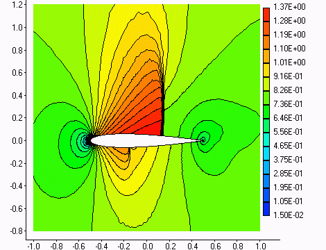
Figure 1. The Mach number contours for the NACA 0012 transonic airfoil (grid with 14973 elements). 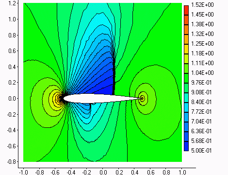
Figure 2. The pressure contours for the NACA 0012 transonic airfoil (grid with 14973 elements). 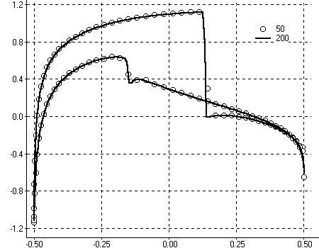
Figure 3. The pressure coefficient distribution for the NACA 0012 transonic airfoil. Dots - grid with 4075 elements (50 grid points on upper and lower surfaces of airfoil); Line - grid with 14973 elements (200 grid points on upper and lower surfaces of airfoil). |
| Mach number | Angle-of-Attack (deg) | Reynolds number |
|---|---|---|
| 0.7 | 1.49 | 9.0e6 |
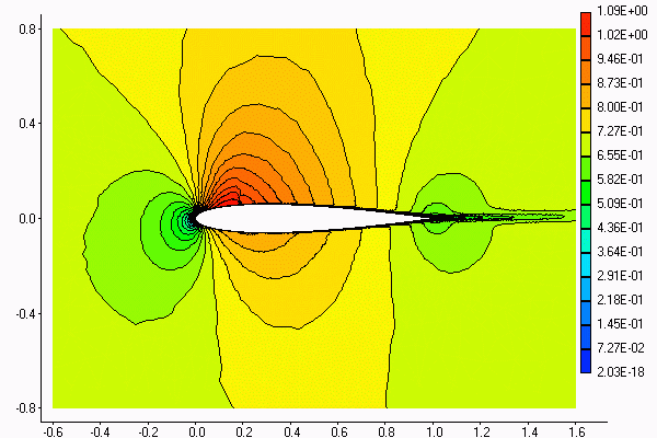
Figure 4. The Mach number contours for the NACA 0012 transonic airfoil. 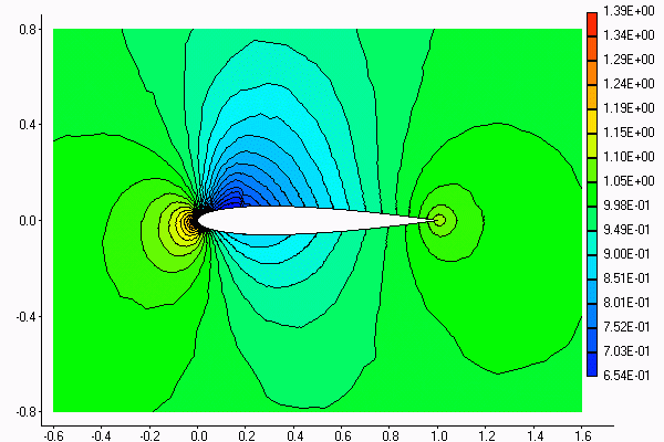
Figure 5. The pressure contours for the NACA 0012 transonic airfoil. 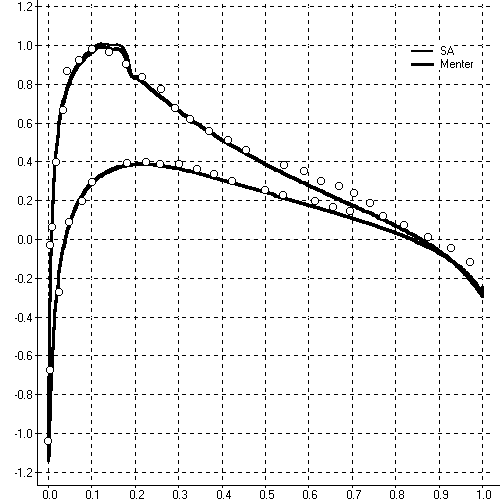
Figure 6. The pressure coefficient distribution for the NACA 0012 transonic airfoil. Lines - simulation with turbulence models of Spalart-Allmares and SST Menter. Points - experiment. |
| Mach number | Angle-of-Attack (deg) | Reynolds number |
|---|---|---|
| 0.7 | 4.0 | 4.0e6 |
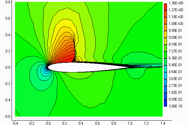
Figure 7. The Mach number contours for the NACA 0012 transonic airfoil. 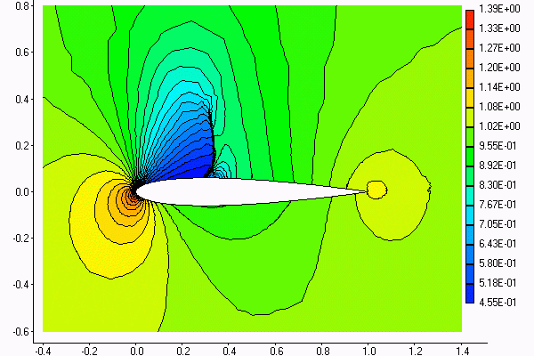
Figure 8. The pressure contours for the NACA 0012 transonic airfoil. 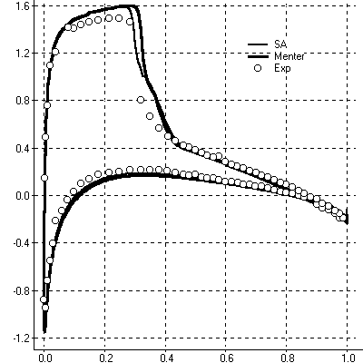
Figure 9. The pressure coefficient distribution for the NACA 0012 transonic airfoil. Lines - simulation with turbulence models of Spalart-Allmares and SST Menter. Points - experiment. |